Flexible PCB vs Rigid PCB — Which One Does Your Design Actually Need?

As a flexible PCB manufacturer with 25+ years of experience, Kejie PCB works with engineers daily on exactly this decision. Choosing between a flexible and rigid PCB isn’t just a materials decision — it affects your assembly process, your enclosure design, your weight budget and your long-term reliability. This guide walks through the key differences, typical applications, and the questions you should be asking before committing to either.

The Flexible Printed Circuit Boards (FPCB) market is expanding rapidly as industries demand lighter, thinner, and more durable electronic components. With the ability to bend, fold, and integrate seamlessly into compact devices, FPCBs are becoming essential in consumer electronics, automotive electronics, medical devices, and wearable technology.

As demand rises across these sectors, FPCBs are transforming product design with their lightweight structure, durability, and space-efficient properties. Driven by the push for miniaturization, high-speed performance, and design flexibility, FPCBs are positioned to remain at the forefront of technological innovation.
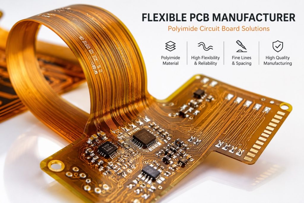
flexible PCB manufacturer polyimide circuit board

IPC-2223 flexible PCB design standard

What Is a Flexible PCB?

A flexible printed circuit board (FPC) is built on a polyimide substrate that can bend, fold or flex during use or assembly. Unlike rigid FR4 boards, flexible PCBs can conform to the shape of a product, reduce connector counts and survive repeated mechanical movement without failure.

Common materials include polyimide (PI) and polyester (PET), with copper traces laminated directly onto the substrate. They can be single-sided, double-sided or multilayer depending on complexity.

What Is a Rigid PCB?

A rigid PCB uses a solid substrate — typically FR4 fibreglass — that cannot bend. It is the most common PCB type, used in everything from consumer electronics to industrial control systems. Rigid boards support higher component density, are easier to handle during assembly, and are generally lower cost for standard designs.

Key Differences at a Glance

Flexible PCBRigid PCB
SubstratePolyimide (PI)FR4 fibreglass
Can it bend?YesNo
WeightLighterHeavier
ThicknessThinnerThicker
CostHigherLower
AssemblyMore complexStandard
Best forWearables, medical, aerospaceIndustrial, consumer, telecom

When Should You Choose a Flexible PCB?

Flexible PCBs are the right choice when:

Your product is medical or aerospace grade — flexible PCBs offer excellent vibration resistance and can be conformal coated for harsh environme

Space and weight are constrained — flexible boards can be folded into tight enclosures where a rigid board simply won’t fit

Your design has moving parts — dynamic flex applications like hinges, rotating joints or wearable devices require a board that can survive repeated bending cycles

You want to eliminate connectors — replacing ribbon cables and board-to-board connectors with a flex circuit reduces failure points and simplifies assembly

When Should You Choose a Rigid PCB?

Rigid PCBs are the right choice when:

  • Your design is cost-sensitive — rigid FR4 is significantly cheaper than polyimide for equivalent layer counts
  • You need high component density — rigid boards support finer pitch components and tighter trace routing more easily
  • Your assembly process is standard — rigid boards run through standard SMT lines without the handling complexity of flex
  • Your application is static — if the board never needs to bend or flex in use, there is no benefit to paying for flexible substrate

What About Rigid-Flex PCBs?

If your design needs elements of both — for example, a rigid section for component mounting and a flexible section to connect two parts of an enclosure — a rigid-flex PCB combines both substrates in a single construction. This eliminates connectors entirely while keeping the mechanical stability of rigid boards where you need it.

Kejie PCB manufactures rigid-flex PCBs with blind vias, controlled impedance and polyimide materials. See our Rigid-Flex PCB manufacturing page →

Why Engineers Choose Kejie as Their Flexible PCB Manufacturer

Whether your project calls for flexible, rigid or rigid-flex construction, Kejie PCB’s engineering team reviews every design file manually before production starts. Our free DFM review catches material compatibility issues, bend radius violations and stack-up errors before they cost you time and money.

We manufacture:

  • Flexible PCB — single and multilayer FPC with polyimide materials
  • Rigid PCB — 2–48 layers with FR4 and specialty materials
  • Rigid-Flex PCB — combined constructions with blind vias and controlled impedance

Get a Quote for Your Flexible or Rigid PCB

Kejie Engineering Portal

What do you need today?

Select the service that best matches your project.

PCB Manufacturing

Manufacture a new PCB from your existing design files.

Engineering Services

Recover, reproduce, or reverse engineer an existing PCB.

Additional Services

Request a quote for production support services related to PCB manufacturing or assembly.

Submitting your files only takes 30 seconds
✓ Files Manually Reviewed by PCB Engineers

Project details

Answer only what applies to your selected service. You can leave technical details blank if they are already inside your files.

Rigid PCB Details

Rigid PCB quotation workflow Start by choosing the fastest way for our engineers to review your project.
How would you like to request your quotation? Our engineers can quote from your manufacturing files or from the PCB specifications you enter below.
📁
Project InformationFor complete manufacturing files, this is all we need before upload.
Engineering Information: Low Please provide the minimum PCB specifications required for an accurate quotation.
📁
ProjectIdentify the project and requested quantity.
🏗
PCB ConstructionCore manufacturing specifications for the board.
Finished Board Size (mm) *
Enter the finished board dimensions in millimeters.
🎨
SurfaceFinish, solder mask and silkscreen preferences.
Special RequirementsSelect any features that apply. Leave blank if none or already specified in your files.
📝
Additional NotesOptional instructions for our engineering team.

HDI PCB Details

HDI PCB engineering workflow Choose whether to upload complete manufacturing files or enter the high-density interconnect details manually.
How would you like to request your HDI quotation? HDI projects are quoted fastest when Gerbers, drill files, stack-up, via structure and impedance information are available.
📁
Project InformationFor complete HDI files, this is all we need before upload.
Engineering Information: LowPlease provide the minimum HDI specifications required for an accurate quotation.
📁
ProjectIdentify the project and requested quantity.
🏗
Base ConstructionCore PCB construction details.
Finished Board Size (mm) *
Enter the finished board dimensions in millimeters.
🧬
HDI Build-UpSequential lamination and microvia structure.
🎯
Via TechnologyAdvanced via features that affect manufacturability and price.
📐
Fine Features & ImpedanceLine width, spacing and controlled impedance requirements.
📝
Engineering NotesOptional instructions for our HDI engineering team.

High Frequency PCB Details

High Frequency PCB engineering workflow Choose whether to upload complete RF manufacturing files or enter the RF and microwave PCB details manually.
How would you like to request your high-frequency quotation? RF projects are quoted fastest when stack-up, material, impedance and operating frequency information are available.
📁
Project InformationFor complete RF files, this is all we need before upload.
Engineering Information: LowPlease provide the minimum high-frequency PCB specifications required for an accurate quotation.
📁
ProjectIdentify the project and requested quantity.
📡
RF MaterialHigh-frequency substrate and dielectric requirements.
🏗
Board ConstructionCore manufacturing details for the RF board.
Finished Board Size (mm) *
Enter the finished board dimensions in millimeters.
〰️
RF PerformanceOperating frequency and impedance requirements.
Special RF RequirementsSelect any RF-specific manufacturing requirements that apply.
📝
Engineering NotesOptional instructions for our high-frequency PCB engineering team.

Flexible PCB Details

Flexible PCB quotation workflow Choose the fastest way for our engineers to review your flex project.
How would you like to request your quotation? Our engineers can quote from your manufacturing files or from the flexible PCB specifications you enter below.
📁
Project InformationFor complete manufacturing files, this is all we need before upload.
Engineering Information: LowPlease provide the minimum flexible PCB specifications required for an accurate quotation.
📁
ProjectIdentify the project and requested quantity.
🧭
Flexible PCB TypeTell us what kind of flex construction you need.
🏗
Flexible ConstructionCore construction details for the flexible circuit.
Finished Board Size (mm) *
Enter the finished board dimensions in millimeters.
🏗
Rigid SectionRigid area construction details.
Finished Board Size (mm) *
Enter the finished board dimensions in millimeters.
🟡
Flex SectionFlexible area construction details.
🔀
Transition AreaTell us about the rigid-to-flex transition.
🛡
Coverlay & ProtectionProtection method for flexible circuitry.
🧩
StiffenersSpecify stiffener material if required for assembly or support.
〰️
Flex BehaviourHow the circuit will bend or flex during use.
Special Manufacturing RequirementsSelect any flex-specific features that apply.
📝
Additional NotesOptional instructions for our engineering team.

Rigid-Flex PCB Details

Rigid-Flex engineering workflow Choose whether to upload complete manufacturing files or enter the rigid-flex construction details manually.
Do you already have complete manufacturing files? For rigid-flex projects, Gerbers plus stack-up and bend/transition drawings are the fastest path for engineering review.
📁
Project InformationFor complete rigid-flex files, this is all we need before upload.
Engineering Information: LowPlease provide the minimum rigid-flex specifications required for an accurate quotation.
📁
ProjectIdentify the project and requested quantity.
🏗
Rigid ConstructionRigid area construction details.
Finished Board Size (mm) *
Enter the finished board dimensions in millimeters.
🟡
Flex ConstructionFlexible area construction details.
🔀
Flex TransitionRigid-to-flex transition and bend behavior.
🧩
StiffenersOptional support material for connector or assembly areas.
Special Manufacturing RequirementsSelect any rigid-flex features that apply.
📝
Engineering NotesOptional instructions for our rigid-flex engineering team.

PCB Assembly Details

PCB Assembly engineering workflow Choose whether to upload complete assembly files or enter the assembly requirements manually.
How would you like to request your assembly quotation? Assembly is quoted fastest when BOM, Pick & Place, Gerbers, drawings and test requirements are available.
📁
Project InformationFor complete assembly files, this is all we need before upload.
Engineering Information: LowPlease provide the minimum assembly specifications required for an accurate quotation.
📁
ProjectIdentify the project and requested assembled quantity.
🧾
Assembly FilesTell us what assembly data is available.
🔧
Assembly ScopeCore assembly type and side requirements.
📦
Supply ModelWho supplies components and bare PCBs.
🧪
Testing & Post-AssemblyProgramming, test and coating requirements.
📝
Assembly NotesOptional instructions for our PCBA engineering team.

Tell us what you are trying to build

Engineering Services Intake

Engineering review intake This shared intake helps our engineers understand recovery, reverse engineering, cloning, or obsolete PCB reproduction requests before assigning the right review path.
Engineering Information: LowPlease provide the minimum information needed for an engineering review.
📁
ProjectIdentify the board and expected quantity.
🎯
Engineering GoalTell us what result you need from the existing PCB.
📷
Photos & Reference DataPhotos and reference files are optional here but strongly recommended in the upload step.
📝
Engineering NotesDescribe the board, problem, desired output, or any constraints.

PCB Stencil Details

PCB stencil intake Collect the basic stencil information needed for SMT stencil quotation.
📁
ProjectIdentify the stencil request and quantity.
🧩
Stencil SpecificationStencil type, thickness and size information.
Stencil OptionsOptional stencil requirements.

Component Sourcing Details

Component sourcing intake Collect BOM and sourcing requirements so our team can review availability and procurement options.
📁
ProjectIdentify the sourcing request and build quantity.
🧾
BOM & Sourcing ScopeTell us what sourcing support is needed.
Procurement RequirementsOptional sourcing and documentation preferences.
Not sure about all specs? Just enter the quantity and upload your files — our engineers will fill in the gaps.

Upload your files

Gerber ZIP is recommended. You may upload multiple files such as BOM, Pick & Place, drawings, or PDFs.

🔒 Your design files remain confidential and are never shared.

Contact details

Where should our engineering team send the quotation?

Step 2 of 4Continue when ready

Scroll to Top