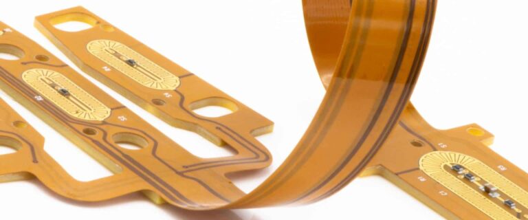
Flexible PCB Manufacturing

Our facilities are equipped for Single-sided, double-sided and multilayer flexible PCB manufacturing with support for controlled impedance, stiffeners, EMI shielding, rigid-flex constructions and advanced surface finishes.

Prototype • Production • Single-Sided • Double-Sided • Multilayer Flex PCBs

Ready to Get Your Flexible PCB Quote?

Upload your Gerber files and project requirements. Our engineering team will review your design and prepare a detailed quotation.

Kejie Engineering Portal

What do you need today?

Select the service that best matches your project.

PCB Manufacturing

Manufacture a new PCB from your existing design files.

Engineering Services

Recover, reproduce, or reverse engineer an existing PCB.

Additional Services

Request a quote for production support services related to PCB manufacturing or assembly.

Submitting your files only takes 30 seconds
✓ Files Manually Reviewed by PCB Engineers

Project details

Choose the quickest way to send your project. Detailed specifications remain available when you prefer to enter them manually.

How would you like to send your project? Use your ready RFQ message, upload the manufacturing package, or enter the selected service specifications manually.
Paste Your Existing RFQPaste your prepared RFQ below. We will preserve your message and review it together with your uploaded project files.
📁
Project InformationEnter the minimum information needed to identify the manufacturing files.

Rigid PCB Details

Rigid PCB quotation workflow Start by choosing the fastest way for our engineers to review your project.
How would you like to request your quotation? Our engineers can quote from your manufacturing files or from the PCB specifications you enter below.
📁
Project InformationFor complete manufacturing files, this is all we need before upload.
Engineering Information: Low Please provide the minimum PCB specifications required for an accurate quotation.
📁
ProjectIdentify the project and requested quantity.
🏗
PCB ConstructionCore manufacturing specifications for the board.
Finished Board Size (mm) *
Enter the finished board dimensions in millimeters.
🎨
SurfaceFinish, solder mask and silkscreen preferences.
Special RequirementsSelect any features that apply. Leave blank if none or already specified in your files.
📝
Additional NotesOptional instructions for our engineering team.

HDI PCB Details

HDI PCB engineering workflow Choose whether to upload complete manufacturing files or enter the high-density interconnect details manually.
How would you like to request your HDI quotation? HDI projects are quoted fastest when Gerbers, drill files, stack-up, via structure and impedance information are available.
📁
Project InformationFor complete HDI files, this is all we need before upload.
Engineering Information: LowPlease provide the minimum HDI specifications required for an accurate quotation.
📁
ProjectIdentify the project and requested quantity.
🏗
Base ConstructionCore PCB construction details.
Finished Board Size (mm) *
Enter the finished board dimensions in millimeters.
🧬
HDI Build-UpSequential lamination and microvia structure.
🎯
Via TechnologyAdvanced via features that affect manufacturability and price.
📐
Fine Features & ImpedanceLine width, spacing and controlled impedance requirements.
📝
Engineering NotesOptional instructions for our HDI engineering team.

High Frequency PCB Details

High Frequency PCB engineering workflow Choose whether to upload complete RF manufacturing files or enter the RF and microwave PCB details manually.
How would you like to request your high-frequency quotation? RF projects are quoted fastest when stack-up, material, impedance and operating frequency information are available.
📁
Project InformationFor complete RF files, this is all we need before upload.
Engineering Information: LowPlease provide the minimum high-frequency PCB specifications required for an accurate quotation.
📁
ProjectIdentify the project and requested quantity.
📡
RF MaterialHigh-frequency substrate and dielectric requirements.
🏗
Board ConstructionCore manufacturing details for the RF board.
Finished Board Size (mm) *
Enter the finished board dimensions in millimeters.
〰️
RF PerformanceOperating frequency and impedance requirements.
Special RF RequirementsSelect any RF-specific manufacturing requirements that apply.
📝
Engineering NotesOptional instructions for our high-frequency PCB engineering team.

Flexible PCB Details

Flexible PCB quotation workflow Choose the fastest way for our engineers to review your flex project.
How would you like to request your quotation? Our engineers can quote from your manufacturing files or from the flexible PCB specifications you enter below.
📁
Project InformationFor complete manufacturing files, this is all we need before upload.
Engineering Information: LowPlease provide the minimum flexible PCB specifications required for an accurate quotation.
📁
ProjectIdentify the project and requested quantity.
🧭
Flexible PCB TypeTell us what kind of flex construction you need.
🏗
Flexible ConstructionCore construction details for the flexible circuit.
Finished Board Size (mm) *
Enter the finished board dimensions in millimeters.
🏗
Rigid SectionRigid area construction details.
Finished Board Size (mm) *
Enter the finished board dimensions in millimeters.
🟡
Flex SectionFlexible area construction details.
🔀
Transition AreaTell us about the rigid-to-flex transition.
🛡
Coverlay & ProtectionProtection method for flexible circuitry.
🧩
StiffenersSpecify stiffener material if required for assembly or support.
〰️
Flex BehaviourHow the circuit will bend or flex during use.
Special Manufacturing RequirementsSelect any flex-specific features that apply.
📝
Additional NotesOptional instructions for our engineering team.

Rigid-Flex PCB Details

Rigid-Flex engineering workflow Choose whether to upload complete manufacturing files or enter the rigid-flex construction details manually.
Do you already have complete manufacturing files? For rigid-flex projects, Gerbers plus stack-up and bend/transition drawings are the fastest path for engineering review.
📁
Project InformationFor complete rigid-flex files, this is all we need before upload.
Engineering Information: LowPlease provide the minimum rigid-flex specifications required for an accurate quotation.
📁
ProjectIdentify the project and requested quantity.
🏗
Rigid ConstructionRigid area construction details.
Finished Board Size (mm) *
Enter the finished board dimensions in millimeters.
🟡
Flex ConstructionFlexible area construction details.
🔀
Flex TransitionRigid-to-flex transition and bend behavior.
🧩
StiffenersOptional support material for connector or assembly areas.
Special Manufacturing RequirementsSelect any rigid-flex features that apply.
📝
Engineering NotesOptional instructions for our rigid-flex engineering team.

PCB Assembly Details

PCB Assembly engineering workflow Choose whether to upload complete assembly files or enter the assembly requirements manually.
How would you like to request your assembly quotation? Assembly is quoted fastest when BOM, Pick & Place, Gerbers, drawings and test requirements are available.
📁
Project InformationFor complete assembly files, this is all we need before upload.
Engineering Information: LowPlease provide the minimum assembly specifications required for an accurate quotation.
📁
ProjectIdentify the project and requested assembled quantity.
🧾
Assembly FilesTell us what assembly data is available.
🔧
Assembly ScopeCore assembly type and side requirements.
📦
Supply ModelWho supplies components and bare PCBs.
🧪
Testing & Post-AssemblyProgramming, test and coating requirements.
📝
Assembly NotesOptional instructions for our PCBA engineering team.

Tell us what you are trying to build

Engineering Services Intake

Engineering review intake This shared intake helps our engineers understand recovery, reverse engineering, cloning, or obsolete PCB reproduction requests before assigning the right review path.
Engineering Information: LowPlease provide the minimum information needed for an engineering review.
📁
ProjectIdentify the board and expected quantity.
🎯
Engineering GoalTell us what result you need from the existing PCB.
📷
Photos & Reference DataPhotos and reference files are optional here but strongly recommended in the upload step.
📝
Engineering NotesDescribe the board, problem, desired output, or any constraints.

PCB Stencil Details

PCB stencil intake Collect the basic stencil information needed for SMT stencil quotation.
📁
ProjectIdentify the stencil request and quantity.
🧩
Stencil SpecificationStencil type, thickness and size information.
Stencil OptionsOptional stencil requirements.

Component Sourcing Details

Component sourcing intake Collect BOM and sourcing requirements so our team can review availability and procurement options.
📁
ProjectIdentify the sourcing request and build quantity.
🧾
BOM & Sourcing ScopeTell us what sourcing support is needed.
Procurement RequirementsOptional sourcing and documentation preferences.
Not sure about all specs? Just enter the quantity and upload your files — our engineers will fill in the gaps.

Upload your files

Gerber ZIP is recommended. You may upload multiple files such as BOM, Pick & Place, drawings, or PDFs.

🔒 Your design files remain confidential and are never shared.

Contact details

Where should our engineering team send the quotation?

Step 2 of 4Continue when ready

Technical Capabilities

Materials & Construction

CapabilitySpecification
Base MaterialPI, FR4, PET Cu
Flexible InsulatorPI 12.5µm–127µm / PET 12.5µm–127µm
Copper TypeRolled Annealed (RA), Electrodeposited (ED)
Copper Thickness12µm–200µm (1/3 oz–6 oz)
AdhesiveAcrylic Adhesive 12.5µm–76µm
CoverlayPI / PET

Layer & Structure Capability

CapabilitySpecification
Layer Count1–8 Layers
Single-Sided FlexSupported
Double-Sided FlexSupported
Multilayer FlexSupported
Rigid-Flex PCBSupported
Rigid-Flex Thickness3–125 mil

Manufacturing Capability

CapabilitySpecification
Minimum Trace Width1.5 mil
Minimum Spacing1.5 mil
Minimum Hole (Mechanical)Ø 0.15 mm
Minimum Hole (Laser)Ø 0.05 mm
Minimum Pad0.25 mm
Hole Tolerance±0.05 mm

Mechanical Capability

CapabilitySpecification
Maximum Size1420 × 400 mm
Minimum Size2.5 × 2.5 mm
Outline Tolerance±0.2 mm
Punch Die Tolerance±0.075 mm
Laser Cut Tolerance±0.05 mm

Surface Finishes

CapabilitySpecification
ENIGSupported
Hard Gold>0.05 µm
Immersion TinSupported
Immersion SilverSupported
OSPSupported

Advanced Features

CapabilitySpecification
Controlled Impedance±10%
EMI Shielding FilmSupported
PI Stiffeners0.075–0.3 mm
FR4 Stiffeners0.2–3.0 mm
Steel Stiffeners0.075–0.5 mm

Flexible PCB Applications

Flexible PCBs are used in compact, lightweight and high-reliability electronic products where space constraints, weight reduction and movement are important design requirements

Medical Devices

Portable diagnostic equipment, patient monitoring systems, wearable healthcare devices and compact medical electronics.

Consumer Electronics

Smartphones, tablets, cameras, gaming devices and other compact consumer products requiring lightweight interconnections.

Wearable Devices

Smart watches, fitness trackers and wearable electronics where flexibility and weight reduction are critical.

Automotive Electronics

Displays, lighting systems, sensors, cameras and space-constrained automotive electronic modules.

Industrial Automation

Sensors, control systems, industrial equipment and electronic modules requiring reliable flexible interconnections.

Telecom

RF modules, antennas, communication equipment and networking products requiring lightweight circuit solutions.

Why Choose Kejie for Flexible PCB Manufacturing?

Engineering support, manufacturing expertise and transparent communication help reduce risk and simplify flexible PCB procurement

Flexible PCB Expertise

Experience manufacturing single-sided, double-sided, multilayer and rigid-flex PCB constructions for a wide range of industries.

Engineering Review

Project files are reviewed before production to identify manufacturability considerations and reduce potential issues.

Prototype to Production

Support for prototype builds, pilot runs and ongoing production requirements with consistent manufacturing quality.

Transparent Communication

Direct communication with our team throughout quotation and production helps reduce delays and misunderstandings.

For designs that combine rigid and flexible sections in a single construction, see our Rigid-Flex PCB manufacturing service. For standard FR4 designs, our Rigid PCB manufacturing page covers full multilayer capability up to 48 layers.

Scroll to Top